DiamondMind 3D Printer Build
8 August 2013
Following success with a Makerbot Replicator 2 I was keen to introduce local teachers to the idea of 3D printing by running a workshop to build one. The folks at MindKits released a tidy version of a RepRap printer that they called the DiamondMind (a collaboration between Mindkits and DiamondAge) which seemed to be a great option for relative novices building a printer. While only a few teachers registered interest I did get a number of secondary students keen to have a go at it so I ordered a kit and we kicked off. The following is the progress made.
Build Progress
It became clear that a number of sessions would be required to build the printer which includes three distinct areas: The frame, the print mechanism, and the electronics.
Day 1: 7 August, 2013
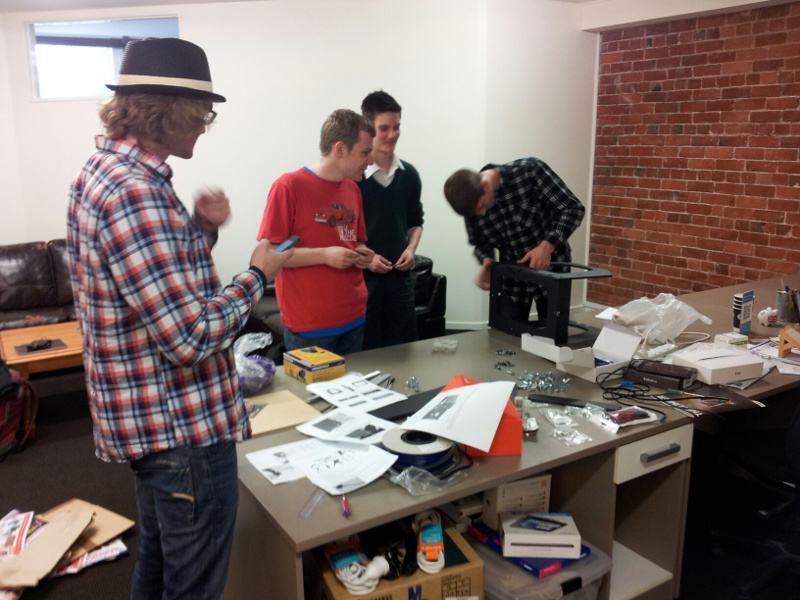
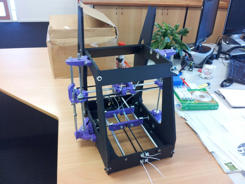
The students turned up (on time and keen). Unpacking was a rather quick process and the students attacked the frame build with alarming effectiveness completing it within half an hour. A bit thrown by this progress and with only half of the mechanism instructions we started working through the Y axis rails and getting a feel for the next steps. We were slowed down by the need to file the axles on the stepper motors to allow for a grub screw and the instructions mentioned heating the plastic with a blow torch (something not included in our current tool kit) so we called it a day.
Day 2: 14 August, 2013
All instructions printed and some initial roadblocks removed ready for the next round of the build.
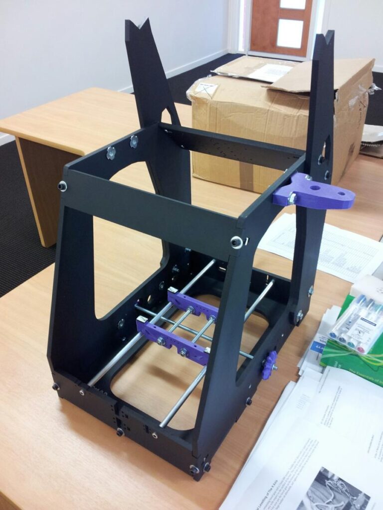
Work began on completing the Y axis and then moved on to the z-axis parts. We took the approach of quickly and loosely attaching parts to get a feel for the overall construction before committing ourselves to tightened nuts and bolts. The threaded rods and related brackets proved a challenge for those of us without strong knowledge of different nut sizes. Very careful attention had to be paid to the instructions as important notes were easy to miss. The final result was a loosely constructed z-axis system that has subsequently been tightened up (and reworked in places). The axel between the two z-axis “kebabs” is still proving difficult as the gears around the stepper motor are not currently meshing well causing skipping.
This Wednesday will likely be a slower moving workshop with a strong focus on accuracy.
Day 3: 21 August, 2013
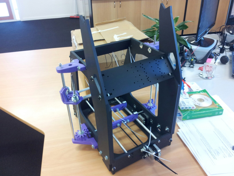
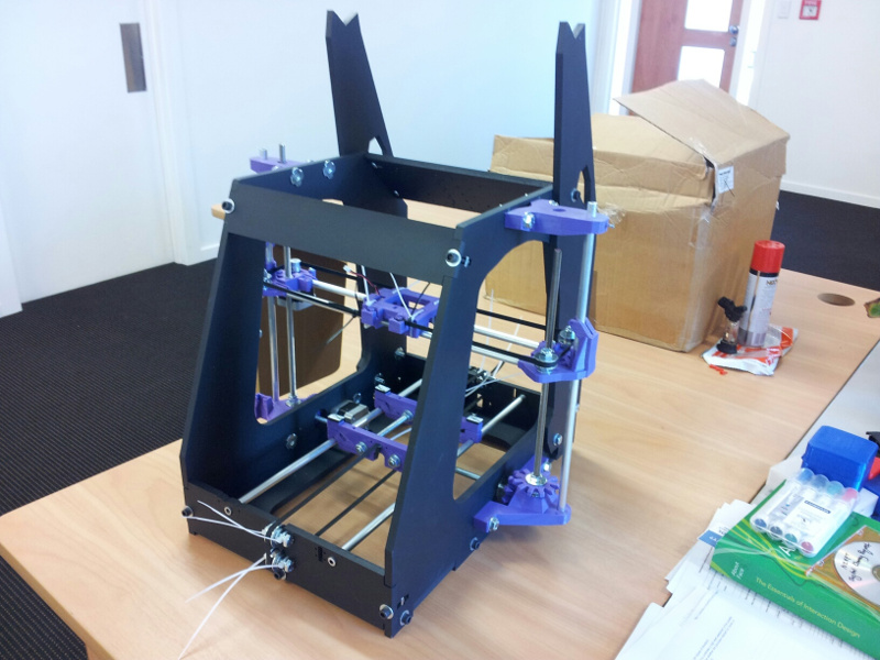
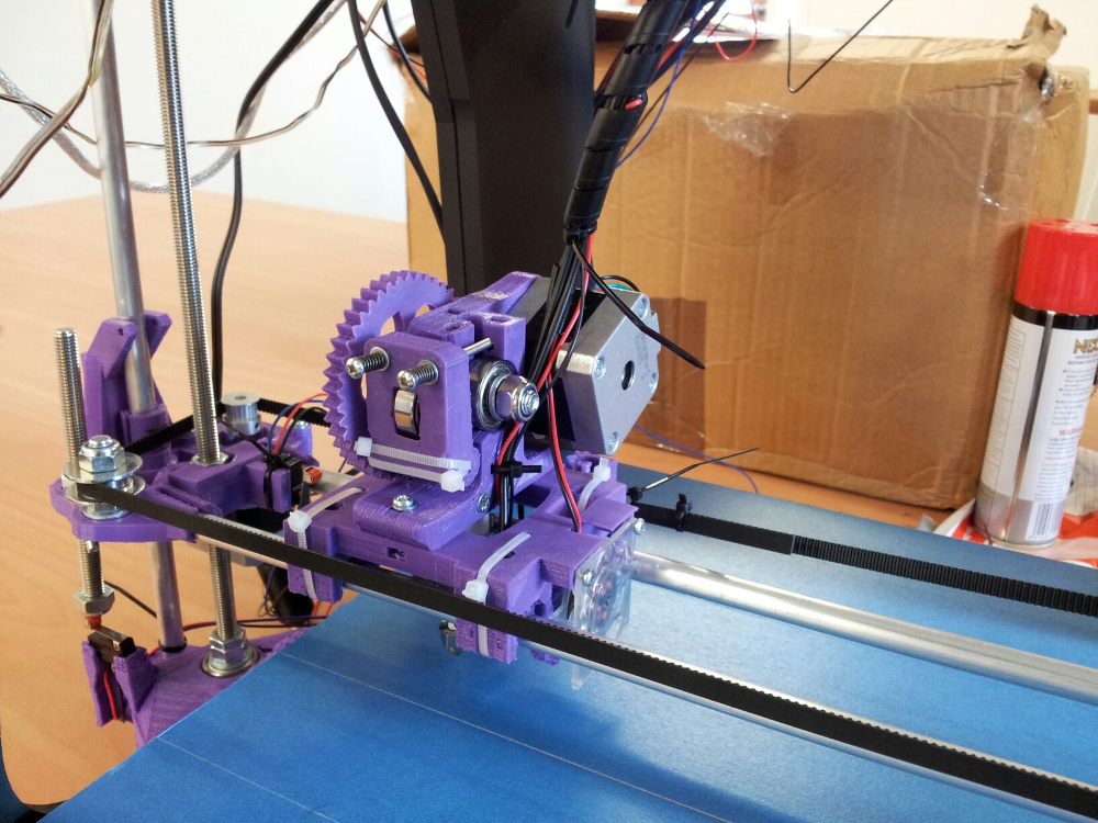
The final mechanical build and first go at the extruder. A couple of the students focused on building up the extruder while the rest of us focused on tightening up the mechanical build. The z-axes continued to be tricky to get aligned and working smoothly but after much reworking and some judicious use of a jet flame lighter to soften plastic the final structures seem to be together and working.
The belt went on to the x-axis and pulled everything tight so the overall frame is now quite solid. Some of the printed gears were a little warped and required some thought about positioning so that they meshed correctly. Swapping them around with the few extra parts in the kit helped find a balance between good printed parts and alignment on the frame.
The Extruder build went well with the majority of the frame and feed mechanism set up really well but came to a halt due to some missing wiring. A few holes need to be drilled to attach the actual extruder head to the body but other than that next time should be all about levelling the extruder and moving on to the electronics. With luck we should be attempting the first print in a couple of sessions.
Day 4: 28 August, 2013
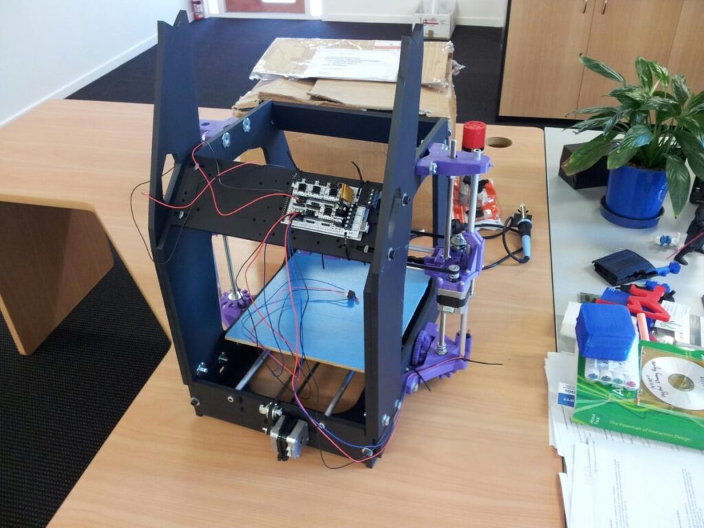
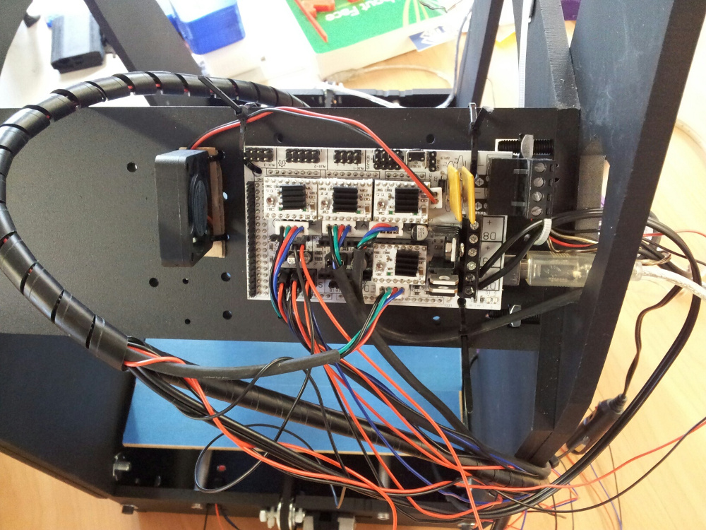
An initial attempt at the electronics set up today. Some missing cables slowed down the basics but the extruder was fitted and the board was attached to the frame. The instructions were a little light around removing jumpers from the stepper controllers but some help from the group sorted that out. The wiring instructions for the fans was also incomplete but again some external advice got us through. The stopper switches have been soldered and connected to the frame and board. The next step will be to continue with the wiring, some testing and, if the missing parts arrive in time, complete the power supply wiring. The printer is starting to look like it should so looking forward to printing from it soon.
Day 5: 4 September 2013
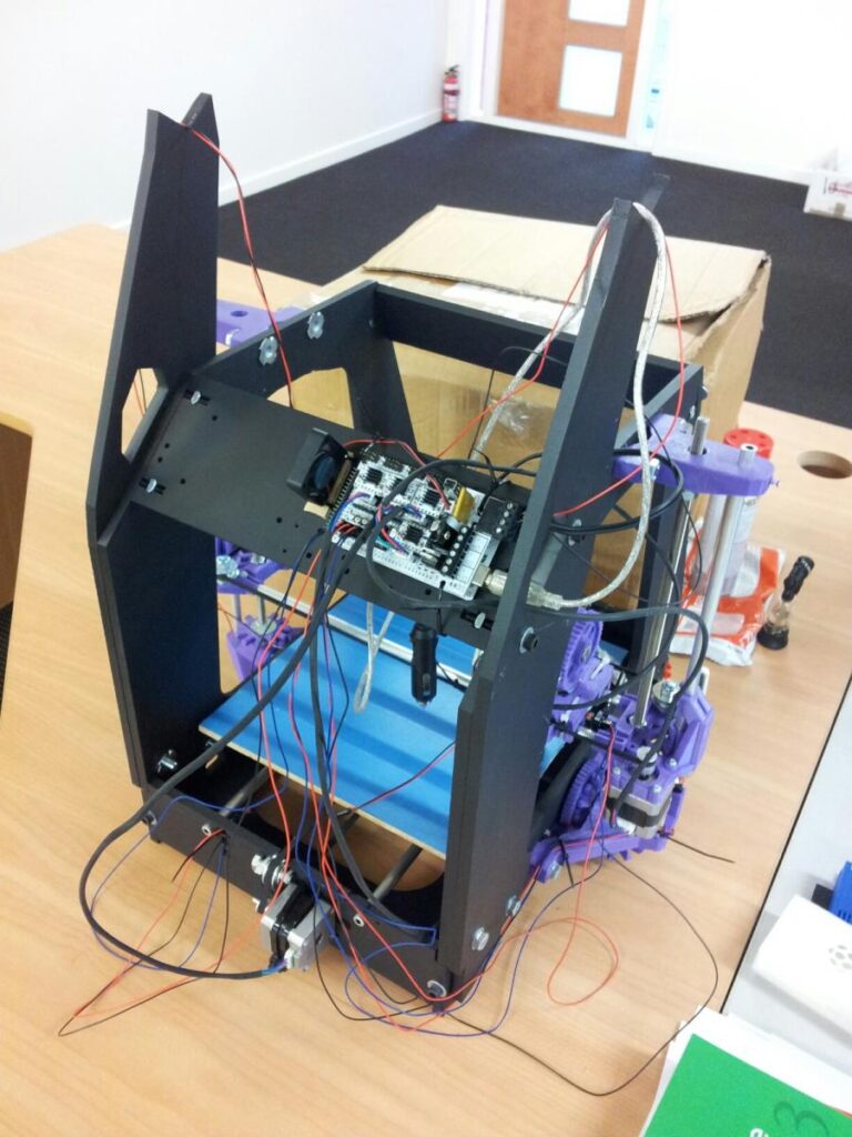
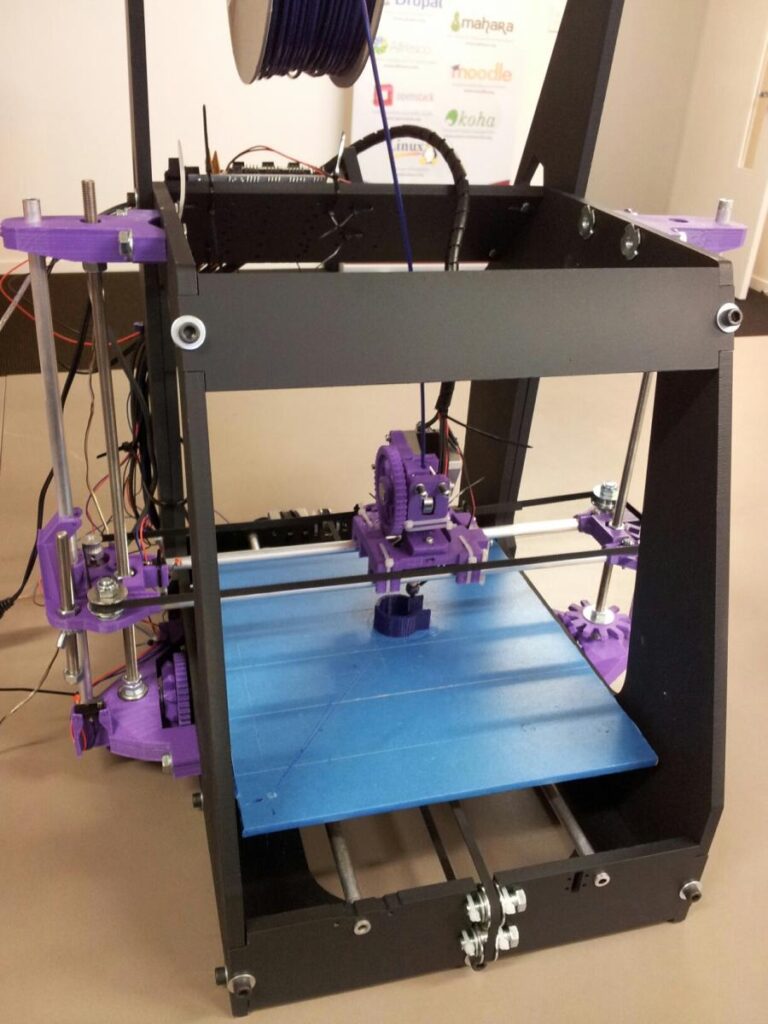
The last of the stopper switches were attached to the frame and wired to the board and some minor adjustment was made to the tension on the X axis to allow it to move smoothly. One of the fans was positioned to cool the stepper controllers on the board and was wired to the 12V pins while the extruder fan and the wiring for the power were wired into a 5V connection. The stepper motors were wired up and while moving the Z axis we noticed the board was lighting up. We decided to connect it to the power and to everyone’s surprise the board lit up and the stepper motors started working. After a brief discussion we uploaded firmware and used Repetier to manually control the stepper motors which, again to everyone’s surprise, were all working and in the correct directions. We added in printer configuration and homed the axes. Once the wiring for the hotend has arrived we will be able to wire up the extruder and test heating the extruder and the filament feed before moving to our first print. Great work by the students to move the build forwards despite confusing instructions and missing parts.
Day 6: 18 September 2013
With the hot end power cable in hand the last of the electronics were completed. The hotend and thermistor were both connected, the extruder was heated up and we were able to feed filament through. The LED strip was added in so the printer now has lights. The mechanical parts all continued to work as expected but the manual control seemed to have some arbitrary limits that stopped the extruder from moving beyond a small area on the plate. We were unable to resolve this by editing the firmware or printer configuraton so came to a stop just before printing. Waiting for some advice on next steps to see if we can resolve these limits before doing a test print.
Day 7: 25 September, 2013
Final repairs included reattaching the extruder to the X axis and the heating and thermistor wires to the hotend. We powered it up, heated the hotend up to 230 degrees and let it settle for 10 minutes before feeding filament through the hot end to ensure it was coming through. The old filament that was blocking the hotend finally gave way and we had filament coming through cleanly. The first print was a space invader that printed perfectly and about .23 layer height and 40% fill. The next print attempt was a cable clip for the wiring at the back of the machine and this was a monumental failure with a lot of plastic noodles being created. After reworking the z axis home and some minor alterations to the level of the plate it printed successfully. The prints seem to be coming out consistently now and after applying some silicon spray to the y axis runners an awful sqeak has been reduced to the quiet burbling good 3D printers should make. The students are now free to do some modelling and print. Despite some frustrations along the way I call this a successful build and have enjoyed working with the students.
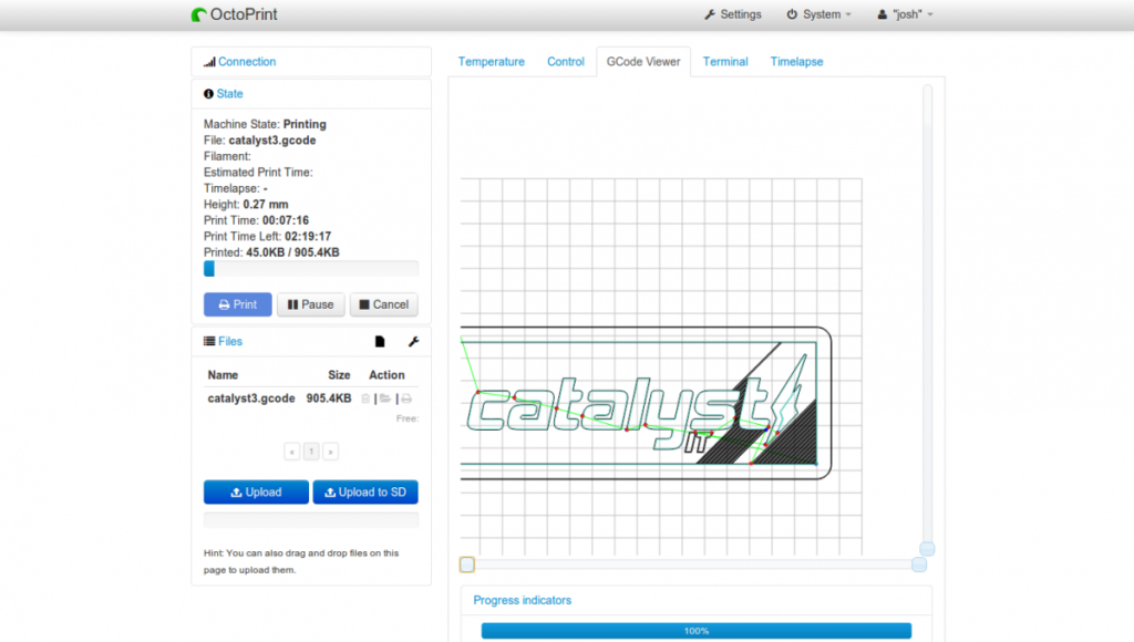
Printing with OctoPrint
With a Rasberry Pi sitting around doing very little the logical step has been to connect the printer to it so we can set up prints remotely. Using the OctoPrint project via the OctoPi image for Raspberry PIs we installed on to a spare SD card and then set up wireless access to the PI. Heading to th eIP address of the PI via a browser resulted in a GUI that allowed us to upload a gcode file and control the printer. We got a bit excited at this point and tried to add a webcam resulting in a Raspberry PI that kept rebooting. Pulled the web cam off and moved everything into another room to test. OctoPrint picks up the printer really well and so far we have two successful prints. The camera would be useful.