3D Printing: Inkscape to 3D
4 June 2013
This resource works through a simple process for taking vector images created in Inkscape to the 3D modelling application OpenSCAD and exporting them to a format suitable for 3D printing.
Resources
Inkscape: http://inkscape.org
OpenSCAD: http://www.openscad.org/
Working files: Robot Files (.zip)
License: Creative Commons
Inkscape
Creating an image

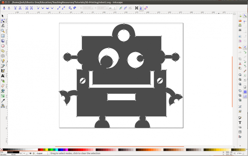
The first challenge is to create an image that is suitable for 3D printing. We are going to create an image and then give it depth by extruding it in the 3D modelling tool. Our image needs to be a solid object which means everything needs to join up to something else. It is fine to have holes in the image but solid objects always need to be connected to something else. We are going to use this robot in this tutorial. Notice how the pupils in the eyes are connected to the edge of the eye? If we did not do this the pupils would print as separate objects and not be connected to the body in the 3D printed object.
Setting the size
The first step is to set the dimensions of the page and the image to millimeters. The final object will print at this size without the need to scale later. In Inkscape go to the File menu and select Document Properties. Under Custom Size select millimeters from the Units list and set the width to 80 and the height to 68. If the robot image is not inside the new page size move it inside until it looks like this:
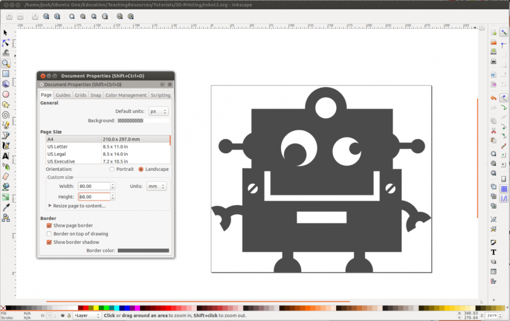
Note: The bottom left corner is 0,0 and everything sizes from there. If you select the drawing the values for X and Y positioning will appear at the top of the screen.
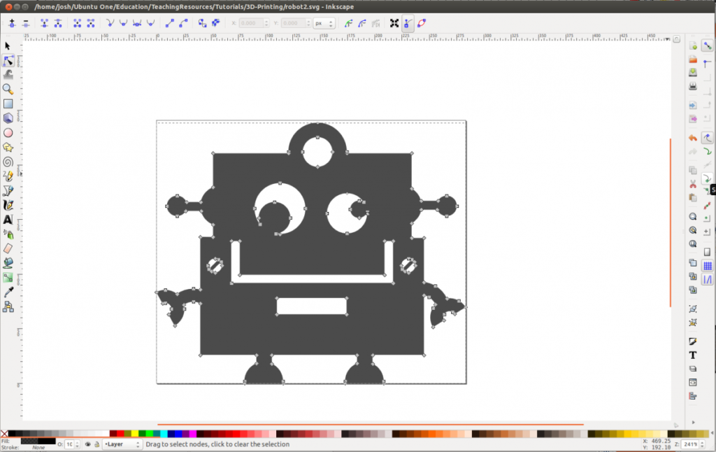
Creating and Editing Paths
The next step is to make everything into a Path and make sure they are as simple as possible. If you used the square or circle tools to create Objects in your drawing you will need to convert them to Paths. To do this select the Object and in the Path menu at the top of the screen select Object to Path. Select the Edit paths by nodes tool (F2) ![]() and drawing should change to show a set of points (known as nodes).
and drawing should change to show a set of points (known as nodes).
Note: you may need to simplify the number of nodes if you have a complex drawing or if there are some duplicate nodes (two nodes very close together). Zoom in to look for these types of nodes. They look something like this:
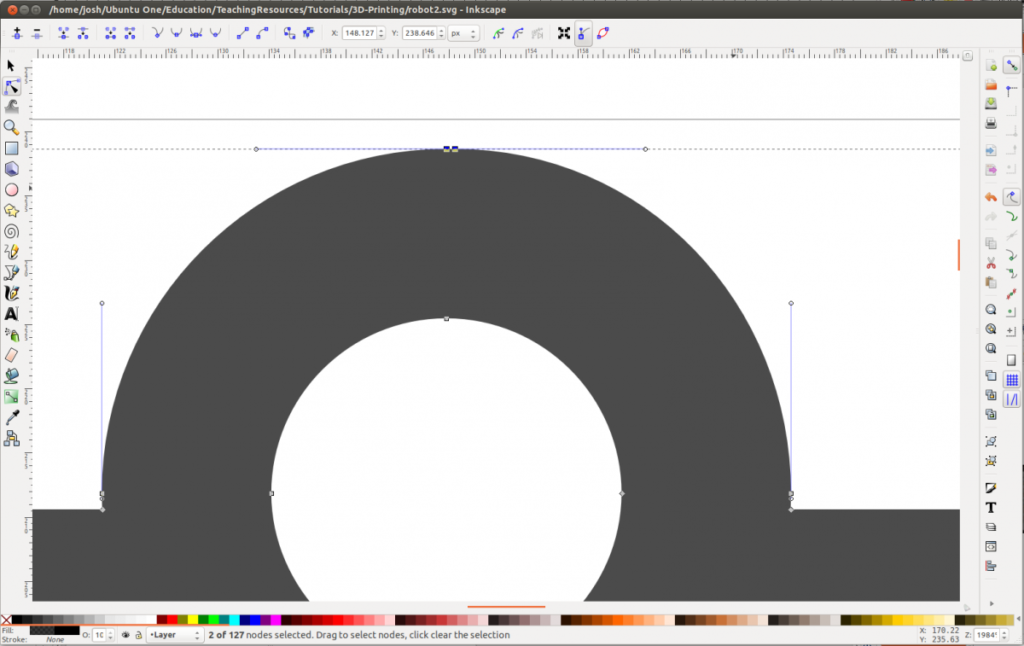
Once these duplicated nodes have been removed the robot drawing looks like this:
Adding Points
The next steps are about getting the drawing ready to export to DXF format so we can open it up in OpenSCAD. OpenSCAD has some limitations around opening files that have curves in them. We are going to prepare the image so it has no curves but still looks like it has curved elements (we don’t want to lose all the circles).Step 1 is to add a few more points … actually a lot of points. Use the Edit paths by nodes tool (F2) and select all of the points in your drawing. Add new nodes by clicking the Insert New Nodes icon 2 or 3 times ![]() .The final image looks like this:
.The final image looks like this:
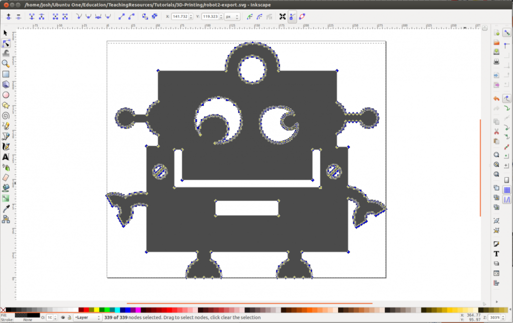
Note: You can select specific parts of the image to add new nodes to. Only the curves really need the extra nodes added.Save this as a new image so you do not lose the original simplified version.
Removing Beziers
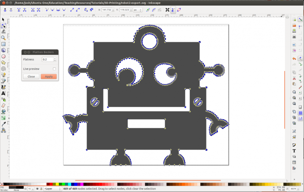
The curves are all currently bezier curves so the next step is to flatten all of the beziers and make them straight lines. Those lines between all of those extra points that we added will flatten but the overall effect will still look like a curve. To flatten beziers select all of the nodes, in the Extensions menu at the top of the screen select Modify Path and then Flatten Beziers. Set the Flatness to 0.2 and click Apply. The image should not visibly change much at all but the curves should all now be flat lines that will work well in OpenSCAD.
Save in DXF format
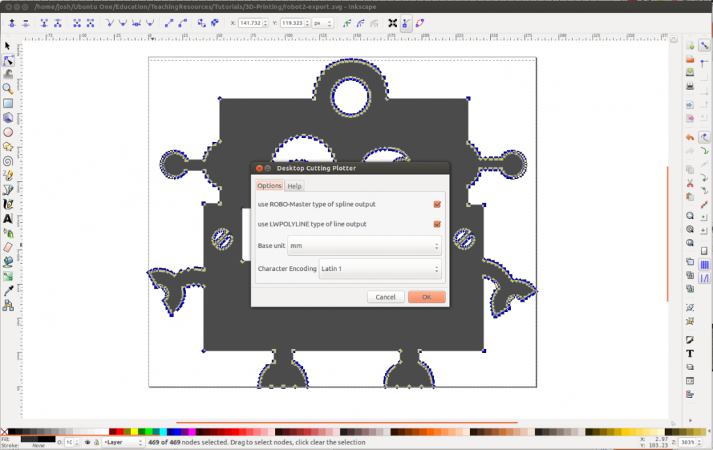
We are going to use the DXF file format to bring the image into OpenSCAD so in the File menu select Save As and choose the Desktop Cutting Plotter (DXF) format from the list of file types.
Save the file as robot.dxf
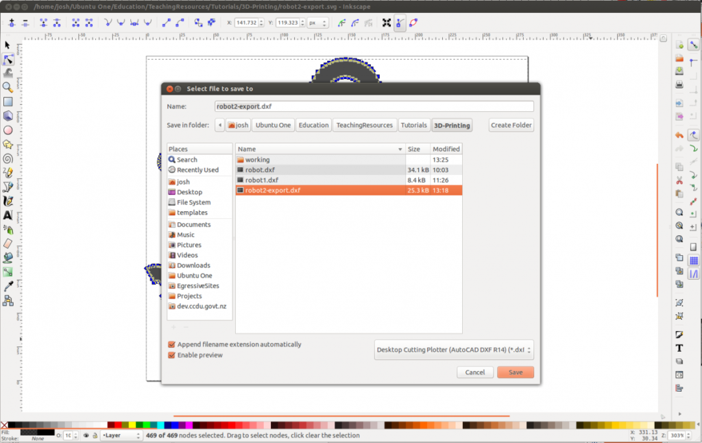
In the save options set the Base unit to millimeters and check both the ROBO-Master type of spline output and LWPOLYLINE type of line output. Character Encoding can be left with the default setting. Click OK. Once the file has saved we have finished with Inkscape.
OpenSCAD
OpenSCAD is a 3D modelling tool that is ideal for creating objects for 3D printing. Instead of interacting directly with the 3D model you write script that OpenSCAD uses to create objects. It can be a little tricky to get used to but it allows for accuracy and creates solid objects both of which are very important in 3D printing. We are going to use a simple extrude function to take our DXF file and give it thickness. This will turn it into a 3D object that we can export for printing. Start up OpenSCAD and you will get something like this:
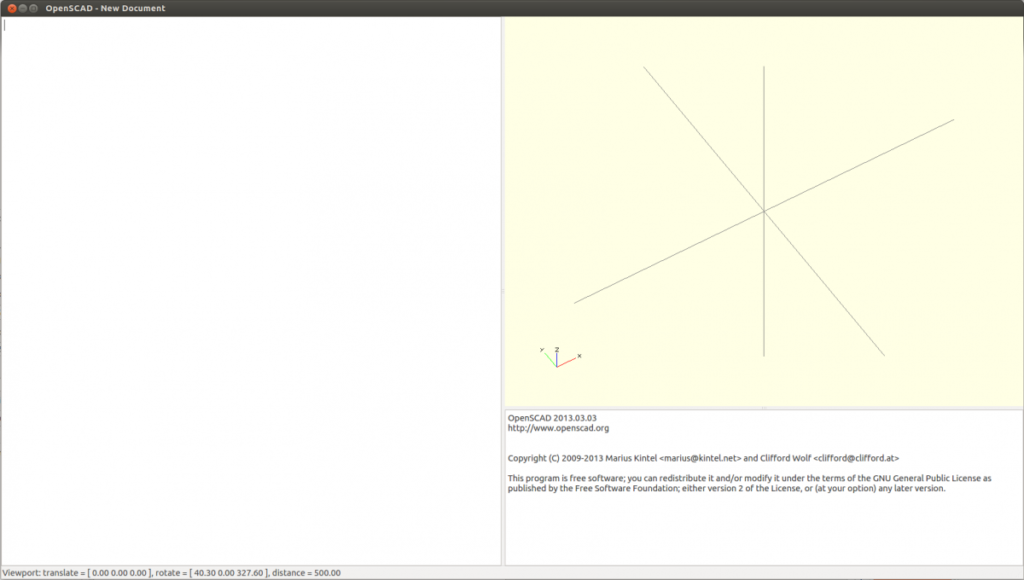
On the left is the area for writing script and on the right is the area the rendered 3D object will appear. Save a new file as robot.scad in the same folder as the robot.dxf file you saved from Inkscape. Note: it doesn’t have to be in the same folder but it makes things easier.
Extruding a DXF file
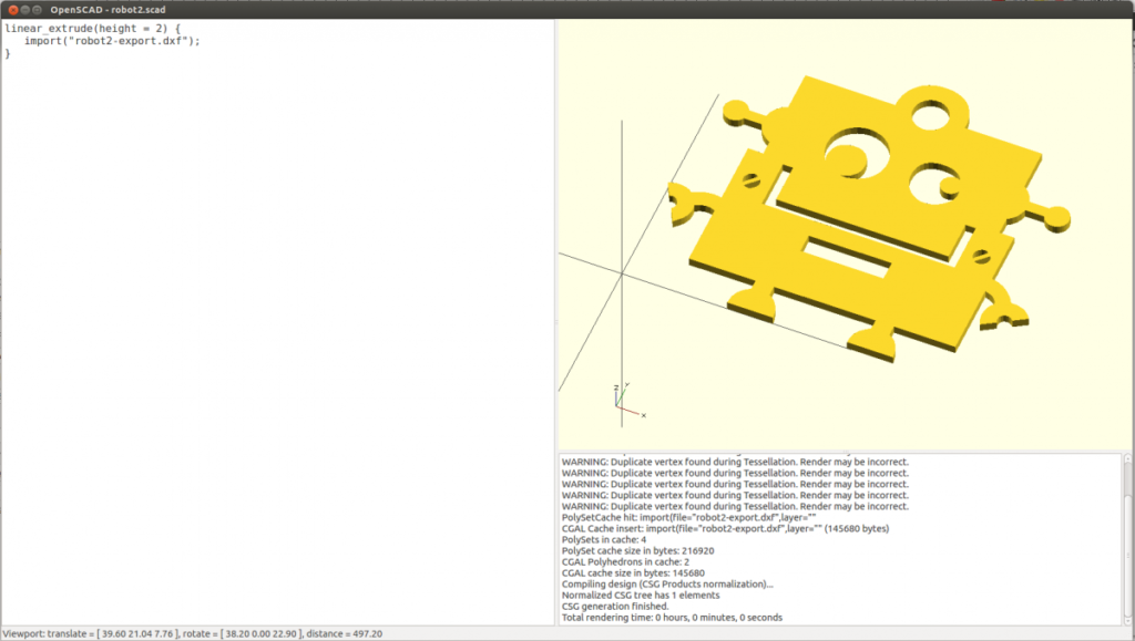
In the script area write the following:
linear_extrude(height = 2) { import(“robot.dxf”); }
Note: There are two parts to this script: 1) The import of the DXF file and, 2) the extrude.
linear_extrude: this is telling OpenSCAD to add thickness to the file that is being imported. In this case it is set to 2. In our case this will be set to millimeters in the final object so it will be 2mm thick
import: this is the file that we want to bring in and extrude.
Render the object
In the Design menu at the top of the screen select Compile (F5) and if all has gone well the object should appear in the right.
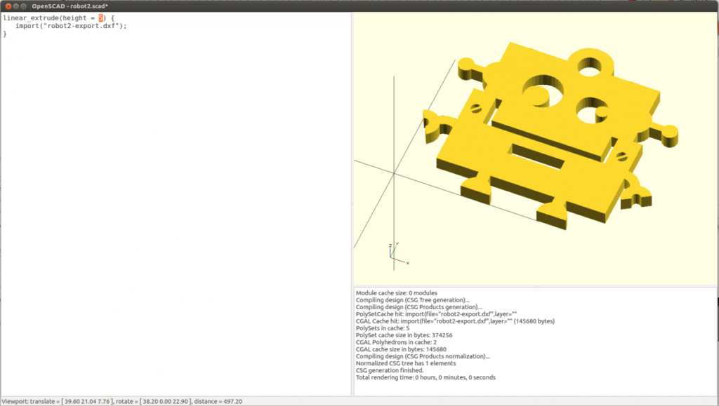
This is where things can go wrong if the file still has curves in it or duplicate points. If it fails for any reason the 3D object will simply not appear. The best bet is to open the image back up in Inkscape and work through the process of removing duplicate points, adding back in multiple points and flattening the bezier curves again. If it has worked and you have an object appearing try changing the extrude value from 2 to 5 and compile the object again (Design > Compile or F5). The object should extrude further to 5mm. The ability to quickly change values like this is a key benefit to using a tool like OpenSCAD.
Exporting for 3D Printing
The final file format will be STL as this is a common format for use in 3D printing.In the Design menu select Compile and Render (F6) to get the final rendered version. It may take a little longer than the standard Compile used previously.Once it has completed select Export STL from the Design menu and save this new file as robot.stl.That is the last stage for OpenSCAD and you should now have a STL file we can bring into a 3D printing tool.
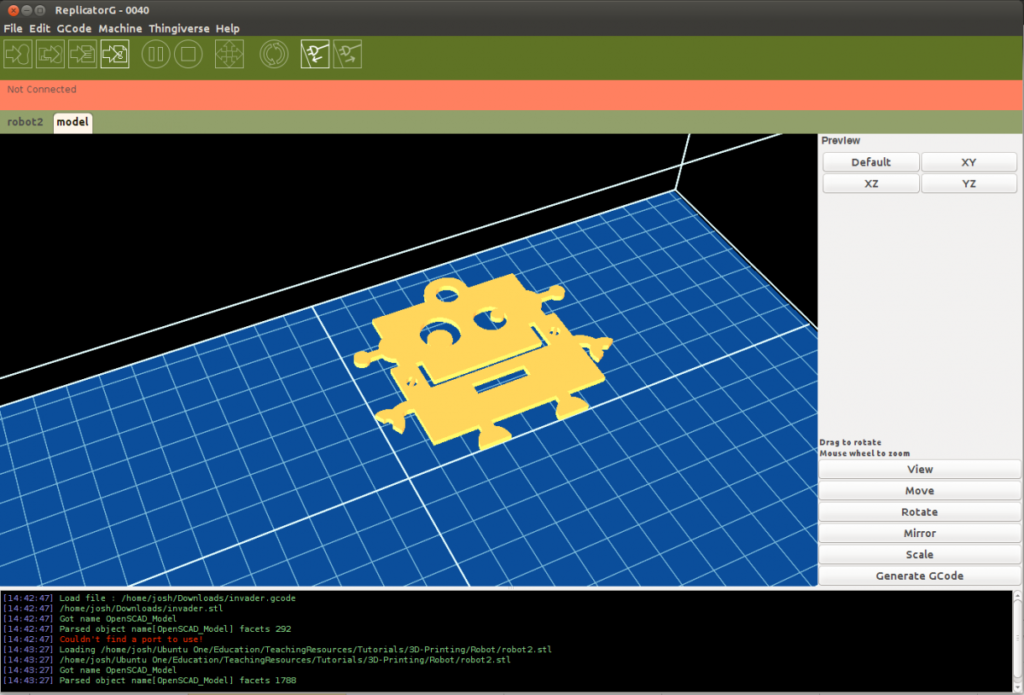
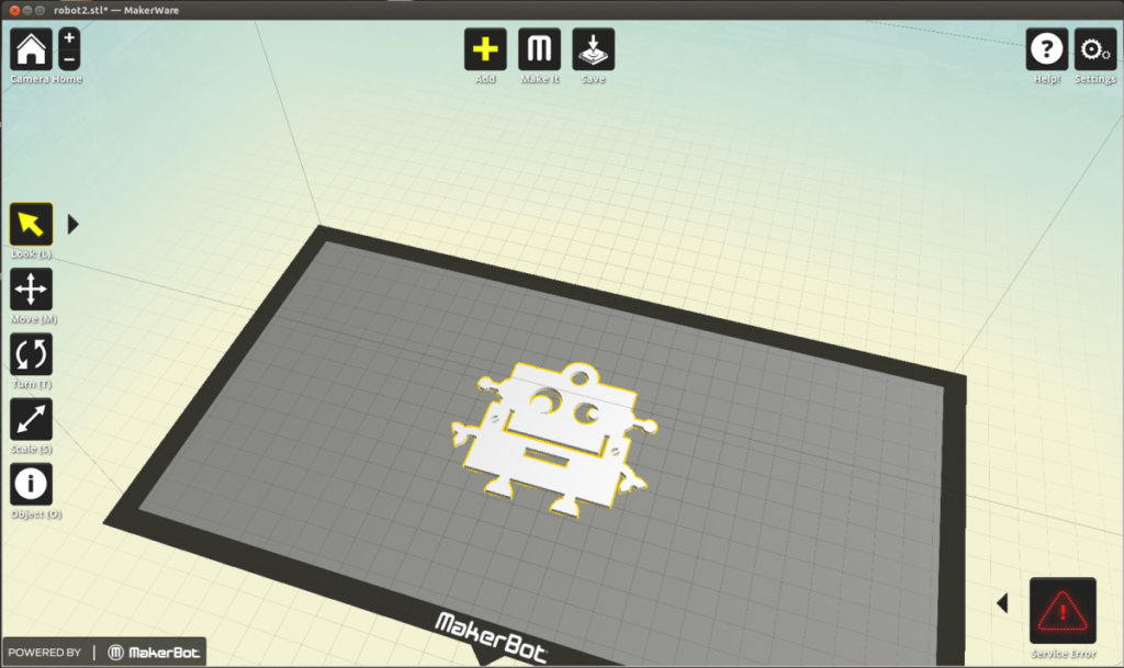
3D Printing
There are a few different tools for sending files to a 3D printer. Common options include:
ReplicatorG: http://replicat.org/
Makerware: http://www.makerbot.com/makerware/
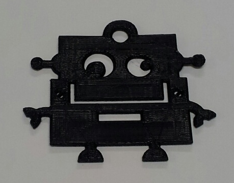
The final result
The final print from a Makerbot Replicator2 looks like this: